Lesson 2:

Linear transmission mechanisms
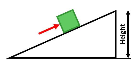
Inclined plane.
Although it is a very simple mechanism, the inclined plane is a linear transmission mechanism, since it transforms a linear movement (that of the arm of the person pushing the box) into another linear movement (that of the box itself). In addition, it allows us to lift an object with less effort, at the cost of increasing the distance that we have to move it.
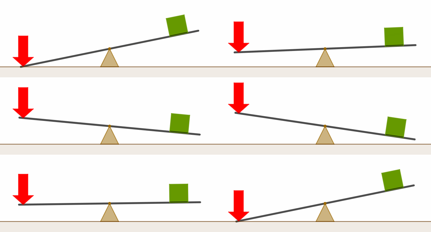
Lever.
The lever is probably the best known linear transmission mechanism. It consists of several parts, that allow us to transform a linear movement on one side of the lever into another linear movement on the opposite side. It is mainly used to lift weights, although, as we will see on pages 4 and 5, tweezers, scissors and even fishing rods are also examples of levers.
Rotatory transmission mechanisms.
Gears.
Gears are the most widely used circular transmission mechanism, and for this reason they will be studied in detail on pages 7, 8, 9 and 10 of this unit. Gears are necessary for many of the appliances that surround us: elevators, vehicles, washing machines, power plants, watches …
For the moment, you just need to know that it is a mechanism that allows transmitting circular motion through wheels with a certain number of teeth on their perimeter and that, depending on the number of teeth on each of the wheels, the turning speed can be increased or decreased.
You must also know that the set of two toothed wheels is what we call a gear, since a single wheel does not constitute a mechanism. As we will see below, there is a wide variety of different gears. The choice of one type or the other will depend on the application for which it is going to be used.
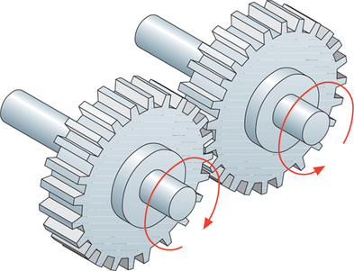
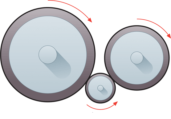
- External gears: are the most common ones. They allow transmitting the movement between two parallel axes at a certain distance. As it can be seen in the drawing on the left, when transmitting the movement through a gear, the direction of rotation changes from one axis to another, if one rotates clockwise the other will rotate counterclockwise and vice versa. For convenience, from now on, the gears will be represented as in the gif on the right, that is, as if they were seen from the front.
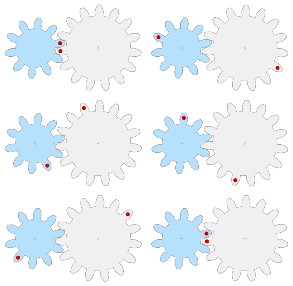
- Internal gears: they are used to transmit movement between two parallel axes that are very close to each other. They are used mainly in mechanisms of reduced dimensions.

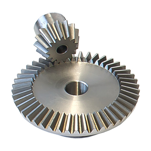
- Bevel gears: they are usually used to transmit movement between two perpendicular axes (which form a 90-degree angle) but there are gears that allow movement to be transmitted between axes that form other different angles.
Gear trains.
The mechanism formed by more than two toothed wheels is called a gear train. They are very useful since they allow us to achieve large reductions or increases in speed, which could not be possible with simple gears. They also allow modifying the direction of rotation of the axes as desired.
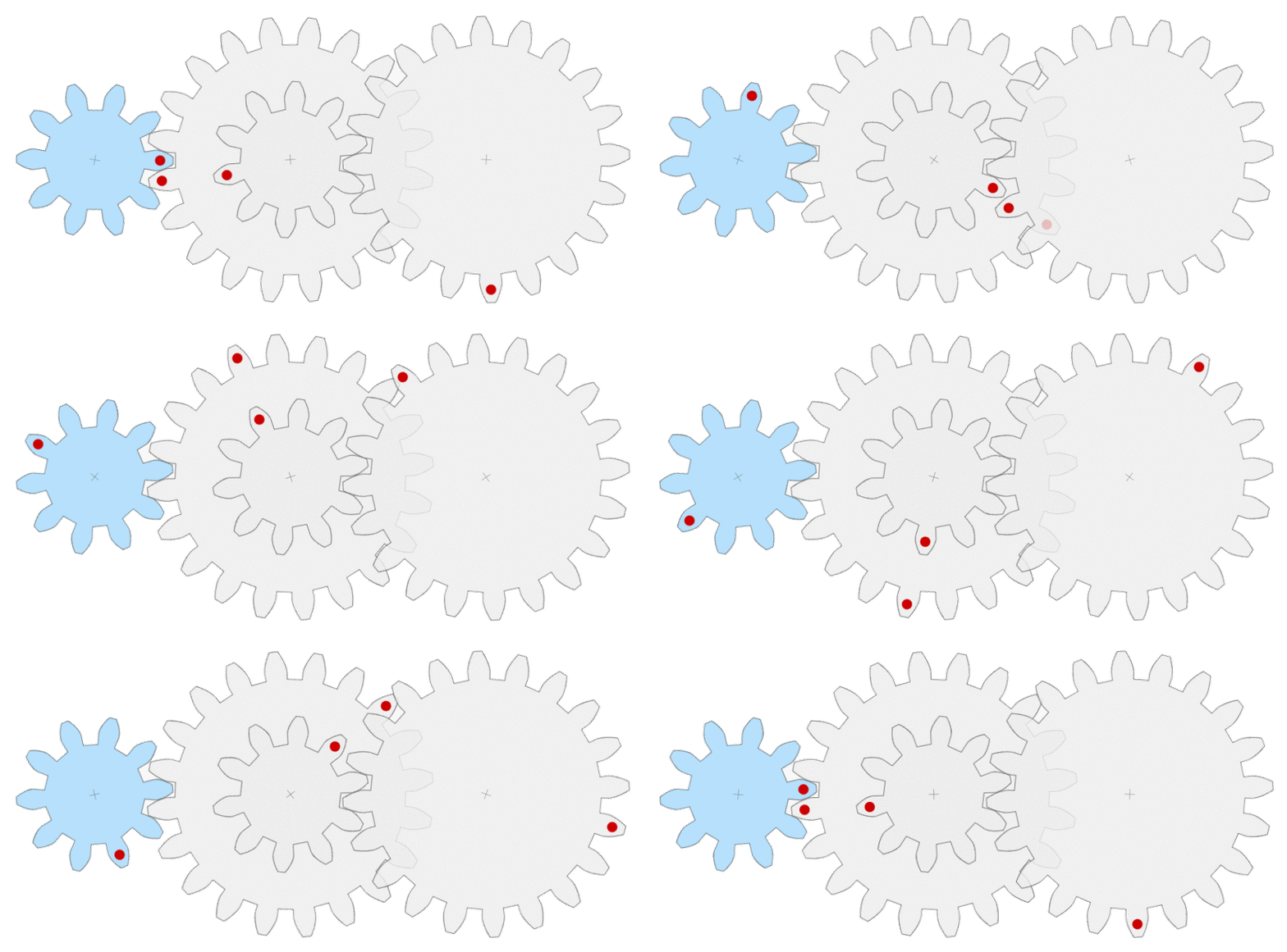
As we will see on page 9, gear trains can be classified into two groups:
- Simple gear trains.
- Compound gear trains.
Belt and pulley.
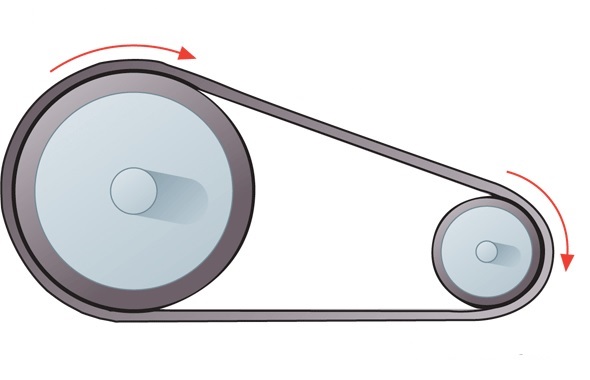
This is a mechanism consisting of two wheels with a groove through which a strap passes. It is used to transmit movement between two axes (usually parallel) that are at a certain distance from one another.
They are used less frequently than gears as they have a major disadvantage: the belt can slip if you try to transmit very high forces. However, they also have the advantage of connecting shafts that are widely separated by simply selecting a belt with the appropriate length.
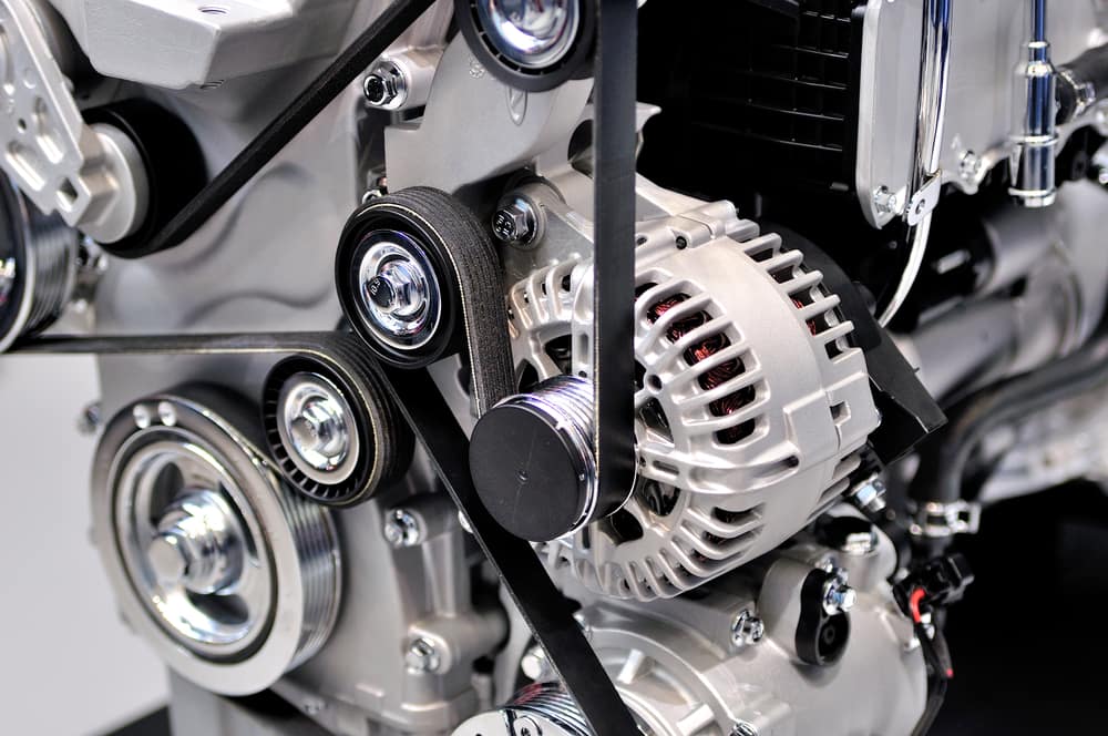
As seen in the drawing on the left, the direction of rotation of the two shafts is the same. In the image on the right a single belt transmits the movement to a set of pulleys (engine of a car):
Chain and sprocket.
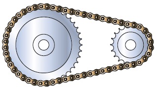
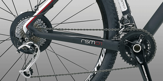
This is a mechanism that aims to combine the advantages of gears and belt pulleys. It consists of a pair of wheels, called sprockets, with special teeth on their perimeter on which a chain can be hooked. This way the movement can be transmitted between axes that are quite far apart (as in pulleys with a belt) and at the same time the teeth of the wheels prevent slippage.
Friction wheels.
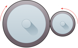
This is a mechanism in which movement is transmitted through friction between two wheels. It is not widely used as it has the disadvantage of gears, the difficulty of connecting shafts too far apart, and the disadvantage of pulleys, since slippage between the wheels can occur.
As with gears, in this type of mechanism the direction of rotation of the shafts changes (image on the left) although an idler wheel can be added to vary the direction of rotation as desired (image on the right):
Worm gear.
It is a mechanism that allows transforming a rotatory movement into another rotatory movement. It has the peculiarity that it transmits the movement between two perpendicular axes, in a similar way to how the bevel gears that we have seen before did. It is made of two parts:
- The worm gear itself: which is a circular rod with a spiral groove on its surface.
- A toothed wheel that meshes with the worm gear.
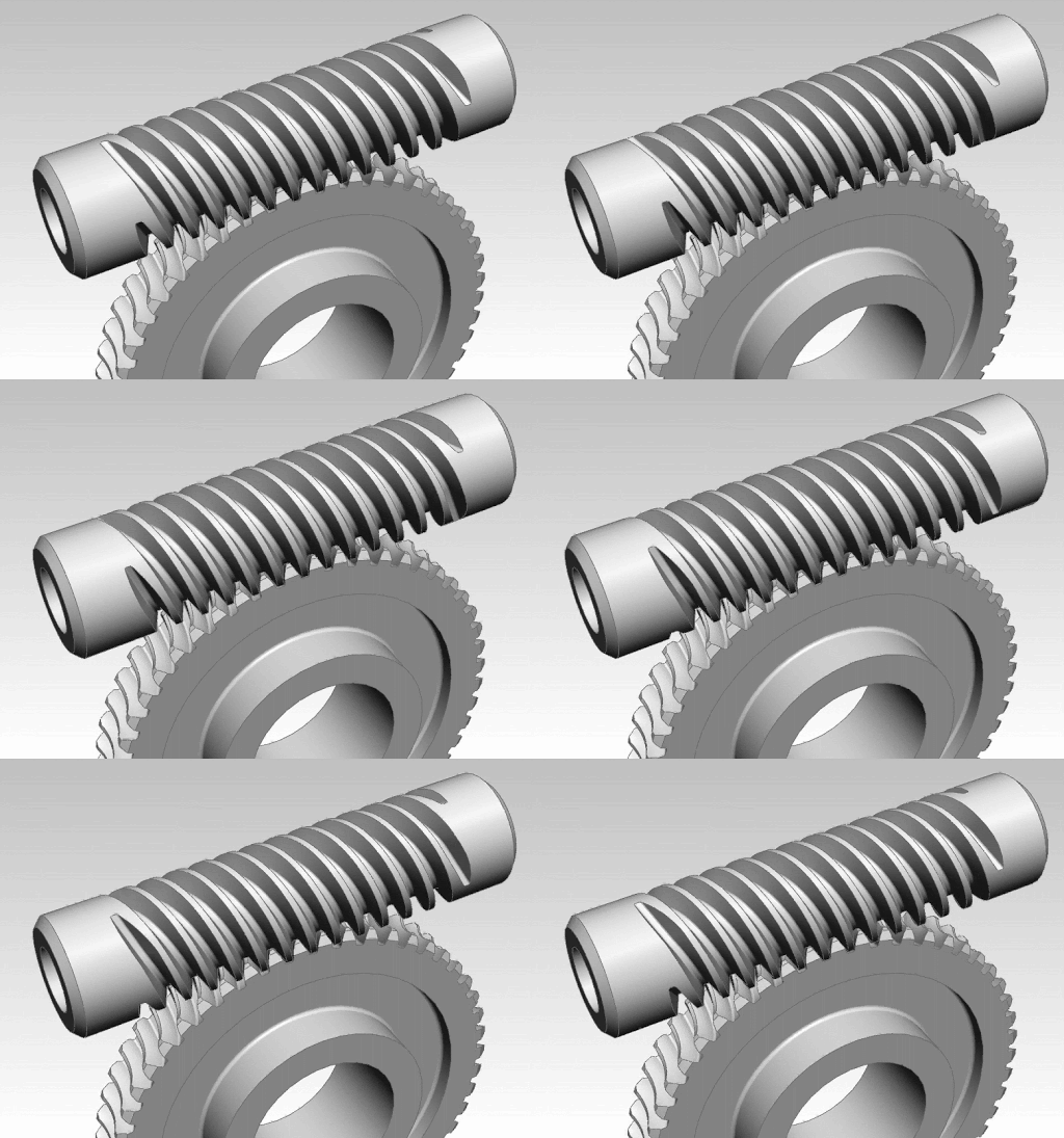
It is not a reversible mechanism, since it is only possible to transmit the movement of the endless screw to the pinion, and not in the opposite direction. It is used in applications where it is necessary to achieve very low speeds. For each complete turn of the worm gear the pinion only advances one tooth, therefore it is the best mechanism to achieve large speed reductions.
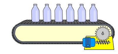
Below you can see a worm gear mechanism used to move a conveyor belt: