Lesson 3:

Transformation mechanisms.
Now we’ll study some of the most used transformation mechanisms as well as their main technological applications. The main goal of this page is to identify the different parts of these mechanisms as well as the type of movement transformation they carry out: linear-rotatoryor rotatory-linear.
Crank – connecting rod.
It is a mechanisms formed by three elements:
- Crank: it is a bar (the blue one in the animation) that rotates around one of its ends and that joins the crank from the opposite end.
- Connecting rod: it is another bar (the green one in the animation) that joins the crank with the piston.
- Piston/slider: It is a piece, usually cylindrical (the one in red in the animation) joined to the connecting rod that moves with reciprocating linear movement.
This mechanism is reversible, what means that it can work in two different ways.
a) Transformation of rotatory motion into reciprocating linear motion: this is the case when the crank is made to rotate and thus the piston is moved linearly.
Air compressors are one of the applications of this mode of operation. There are many automatisms that work thanks to a compressed air system. A good example is the door opening system of a bus. Surely you have sometime heard the noise of the air coming out of the air circuit on a city bus. This noise occurs when the compressed air system has reached excessive pressure and therefore needs to release some of the air.
Any system that uses high pressure air to work needs a compressor to raise the pressure (it would be the equivalent of the battery in an electrical circuit). And precisely one of the most used air compressor models is the one that is based on a connecting rod-crank mechanism, in which a piston absorbs air at low pressure (blue air in the gif) as it moves downwards and compresses it (red air) in the upward movement. The rotary movement of the crank is provided by a motor.
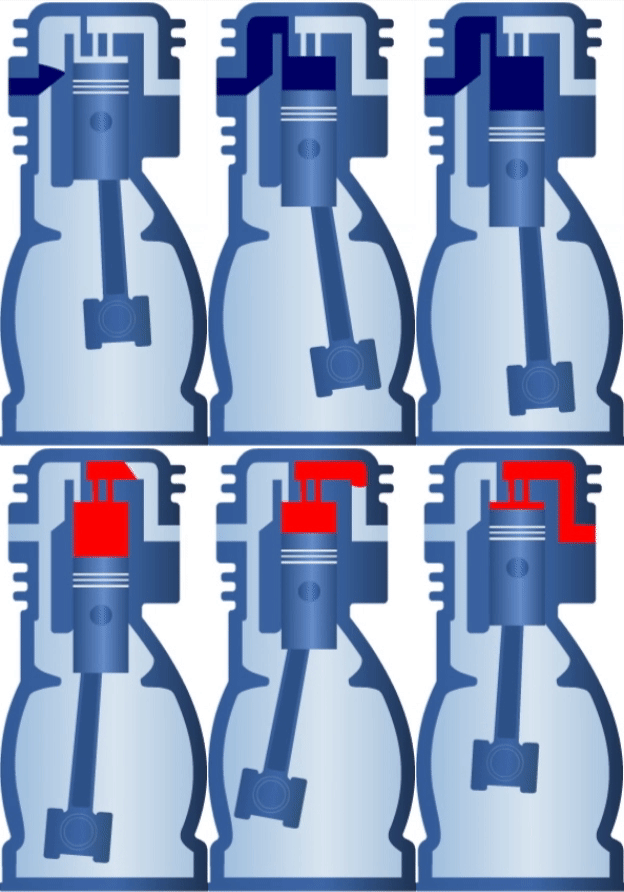
b) The other mode of operation consists of transforming the reciprocating linear movement of the piston into a circular movement: this situation occurs when the piston is forced to move linearly, forcing the crank to rotate.
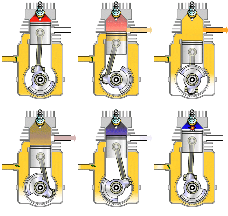
The main application of this mode of operation are combustion engines, that is, those that use a fuel such as gasoline. In these engines, fuel is burned to cause an explosion that moves the piston down inside the cylinder, which is the part inside which the piston is located.
Thanks to the crank-connecting rod mechanism, the linear movement of the piston is transformed into a rotary movement on an axis that has a somewhat particular shape (as you can see in the gif below) called the crankshaft. The crankshaft is joined to the vehicle’s wheels, providing them with the necessary motion to move the vehicle forward.
To increase the power of an engine more than one crank-connecting rod mechanism is connected to the same crankshaft, hence there are 4, 5, 6, 8 and up to 16 cylinder engines. The greater the number of cylinders of the engine, the greater its power.

Eccentric – connecting rod.
Actually this mechanism is quite similar to the previous one. The only difference is that in this case the crank has been replaced by a disk or wheel to which the crank is attached. What makes it possible to transform the circular motion into an alternative linear motion and vice versa is the fact that the connecting rod is not connected to the center of the disk but at a certain distance from it. The disk of the mechanism is called an eccentric wheel, or simply eccentric.
As it happened with the crank-connecting rod mechanism, it is a reversible mechanism, which makes it possible to transform rotatory movements into linear movements and vice versa. It has numerous applications such as some windshield wipers, sewing machines …
Cam – follower.
This is a non-reversible mechanism, since it only allows a rotary movement to be transformed into a linear one. It consists of three parts:
- The cam: It is a piece with a certain shape that is connected to an axis, which provides the rotation movement.
- The roller: transmits the movement of the cam to the follower.
- The follower: it is the rod that moves in a reciprocating linear movement that depends on the shape of the cam.
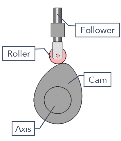
This mechanism is probably the most versatile of all those that transform a rotatory movement into a reciprocating one. This is because any movement can be achieved by varying the shape of the cam surface, as it can be seen in the gifs below.
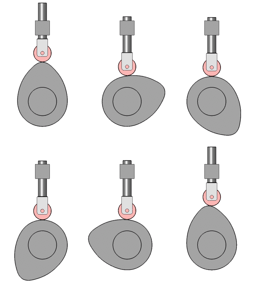
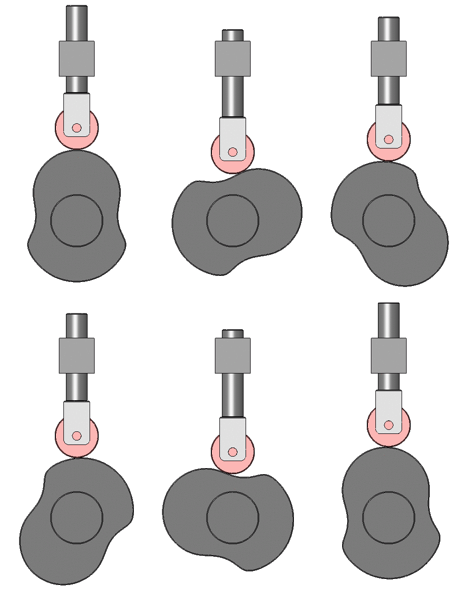
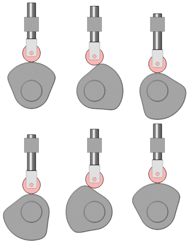
The cam-follower mechanism is used in plenty of technological applications. For example, they are used in vehicle engines to open and close the valves that allow fuel to enter the cylinder where the explosion occurs. Apart from that, cams are used in many other machines in which a movement needs to be automated: in looms, in placement systems for production lines, in water distribution systems …
Rack and pinion.
It is a reversible mechanism that allows transforming a rotatory movement into a linear one and viceversa. Is is made of two parts:
- The pinion: it is a small toothed wheel.
- The rack: which is a metal strip with teeth that fit the ones of the pinion.
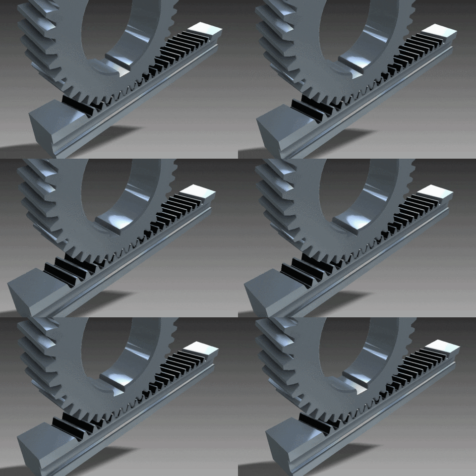
Although it is a reversible mechanism, it is usually the pinion that provides the circular movement to the rack, which transforms it into a linearmovement. It allows fairly precise control of the movement, since depending on the angle turned by the pinion, the rack will move more or less. Its main disadvantage is that it does not allow high speeds.
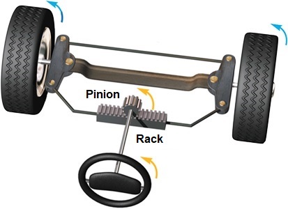
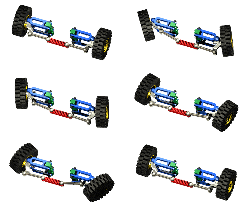
This mechanism is used, for example, in automatic doors of garages and some trains. In these cases, the rack is usually attached to the door so that the pinion can move it when it rotates. It is also used to transmit the movement of the steering wheel to the wheels of vehicles:
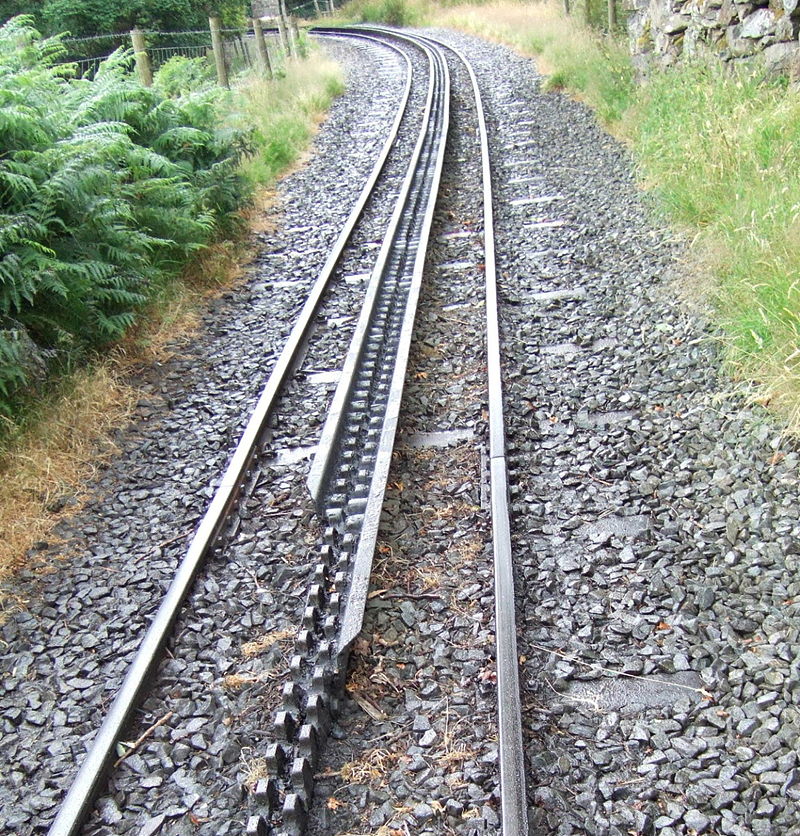
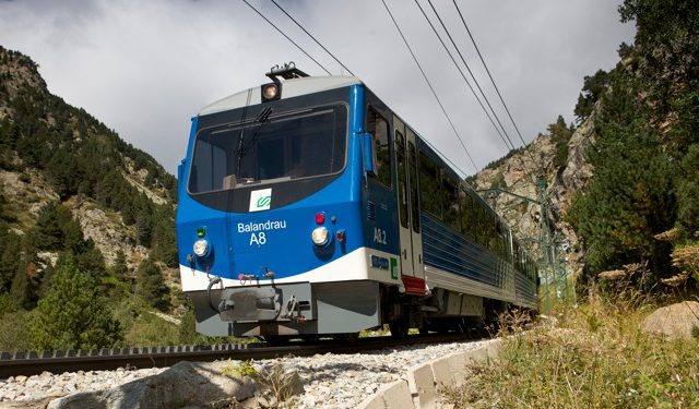
Finally, a very interesting application of this mechanism is in the construction of a special type of train, called rack railway, which is designed to climb very steep slopes. In this kind of train a pinion, which is located at the head of the train, meshes a third rack-shaped rail. In the image, you can see the rack railway of Nuria (Gerona), which, since its inauguration in 1931, made it possible to connect some of the most isolated villages in the Pyrenees.
Other transformation mechanisms.
Although the most widely used mechanisms have been seen above, there are many more mechanisms that have been designed for very specific applications. Two examples of this are the Maltese cross and the Scottish yoke:
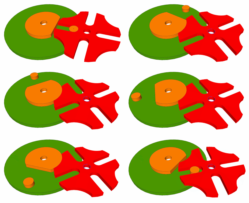
- Maltese cross (or Geneva cross): it is a mechanism that allows transforming a continuous circular movement (that of the green disk) into a discontinuous circular movement (that of the red part, which is properly the Maltese cross). Depending on the number of openings in the cross, the angle rotated per turn can vary. In the gif below, for each turn of the green disk, the Maltese cross makes a quarter turn (90º).
Two applications of this interesting mechanism are:
a) For the movement of watches, although other more precise methods are already used nowadays.
b) In cinema projectors, in which the film must advance intermittently (usually 24 frames per second).
- Scotch yoke: it is a reversible mechanism that allows transforming a rotatory movement into an reciprocating linear movement and vice versa. Compared to the crank-connecting rod mechanism, it has the advantage of having fewer moving parts, which simplifies the design. In addition, the movement generated is less abrupt (softer), what can improve the performance of the machine. It is used in some engines, in air compressors and also to activate valves that regulate the flow in gas and oil pipelines.