Lesson 5:

What is an electrical circuit?
The electrical components that we have seen above are useless on their own.
An electrical circuit is a set of several electrical components connected to each other by conductors, in such a way that the current that leaves the battery can return to it. Electrical circuits do perform some specific function.
Below you can see two very basic circuits:

– In the circuit on the left a bulb is controlled by a push switch, so that the bulb will light up when the button is pressed.
– In the circuit on the right a motor is controlled by a switch, so that in one position the motor rotates while in the other it does not.
Through the following link https://www.tinkercad.com/things/ahgLjQkeiNt you can access the Tinkercad project to check how the circuit works. To do this, click on Simulate and then on the Start Simulation button.
IMPORTANT: to start the simulation you must first sign up in Tinkercad. It’s very simple, since you can use your personal gmail account and it’s totally free. If you are not yet registered, click on the following link and select Create personal account (https://www.tinkercad.com/join).
Since it is not easy to draw in detail each of the components of a circuit, the symbols seen above are often used to draw what is called the electrical diagram of a circuit. The electrical diagrams of the two previous circuits would be:
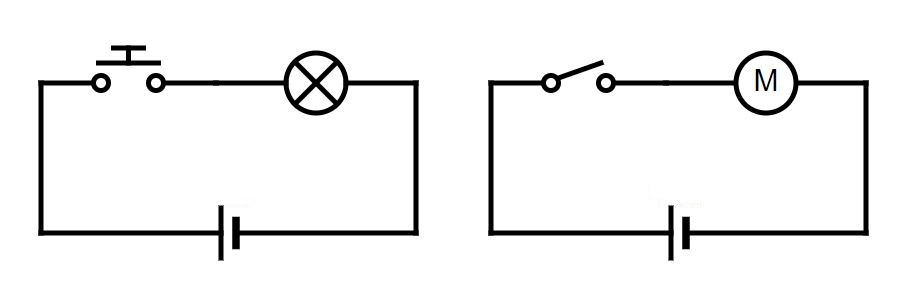
As you can see, in the electrical diagrams the wires are drawn as straight lines to make it easier to understand the operation of the circuit.
Ways to connect components in an electrical circuit.
All the electrical components that we have seen have one terminal (also called pin) through which the electric current enters, called the input terminal, and another terminal through which it comes out, called the output terminal.
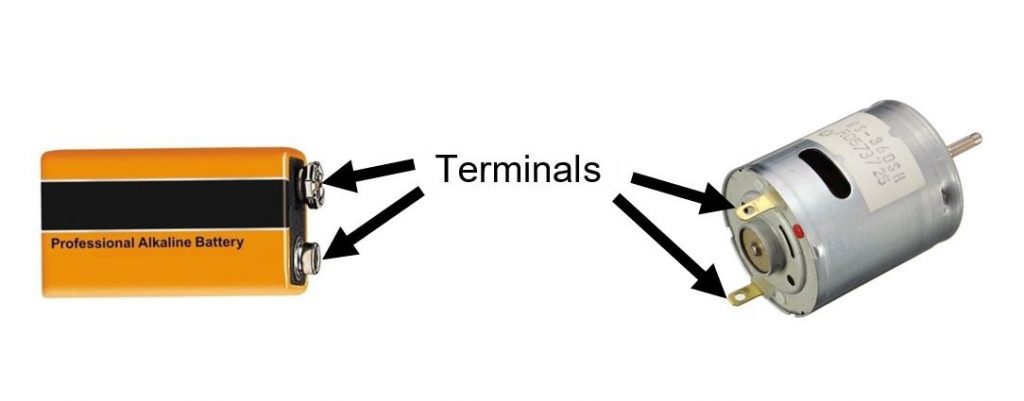
Depending on the way in which the terminals of the components of a circuit are connected, we can distinguish two types of circuit:
1) Series circuit: when the output terminal of one component is connected to the input terminal of the next one. In other words, one component is connected after another. Below you can see a series circuit made of two bulbs:
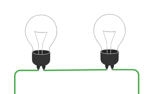
When two or more components are connected in series, the number of electrons leaving the cell is the same as the number of electrons flowing through all the components. Therefore, in a series circuit, the electrical intensity in all the components is the same that leaves the battery.
2) Parallel circuit: when the input terminals and the output terminals of several components are connected together. Below you can see a parallel circuit of two bulbs:
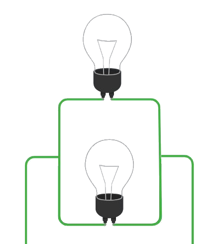
When two or more components are connected in parallel, the number of electrons that leave the battery and the number of electrons that flow through the components is not the same. This is due to the fact that at one point the electrons split among the different components, and then gather before returning to the battery.
Therefore, in a parallel circuit, the electrical intensity in the different components is not the same that comes out of the battery.
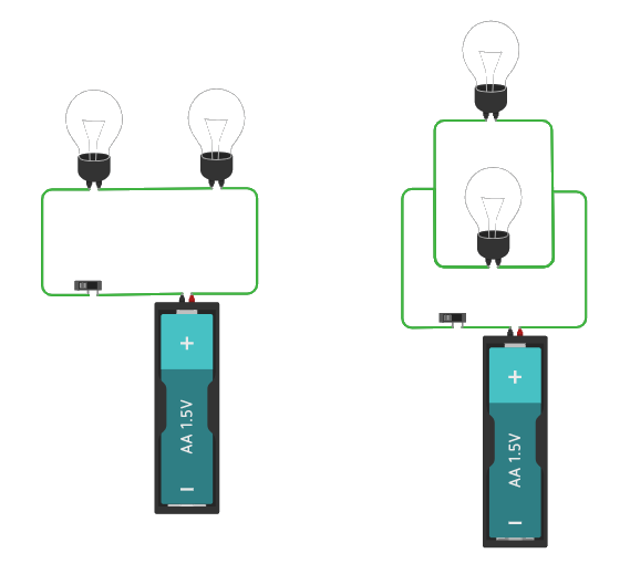
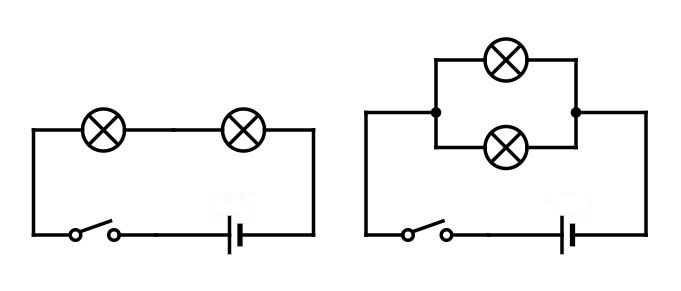
Below you can see two parallel circuits, the one on the left consisting of two bulbs in series and a battery with a switch, the one on the right consisting of two bulbs in parallel and a battery with a switch:
The electrical schemes of the circuits above are…
You can click on the link: https://www.tinkercad.com/things/3FgaS7craZK, to access the Tinkercad project.
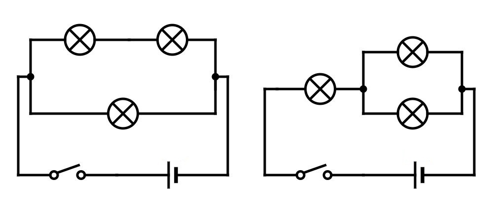
Finally there is a type of circuit, called series-parallel circuit, which is a mixture of the other two types of circuit. Below you can see two examples, but there are many more:

You can click on the link: https://www.tinkercad.com/things/aUZdXGvbBgM, to access the Tinkercad project.
The electrical diagrams of the two previous circuits are: