Lesson 6:

Dimensioning of figures with inner elements.
It is quite frequent to find different inner elements (squares, circles…) inside a figure. This happens, for example, when a hole is represented. When this happens two types of dimensions must be indicated:
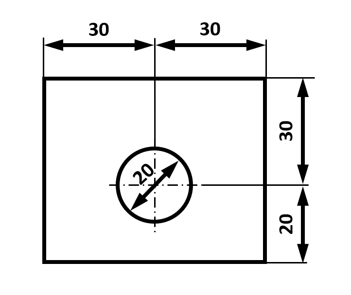
Let’s see two examples. The first one is a rectangular piece with a circular hole in a specific position. In the case of a circle, its position inside the figure must be indicated by writing the distance from its center to the sides of the figure. Both options are okay:

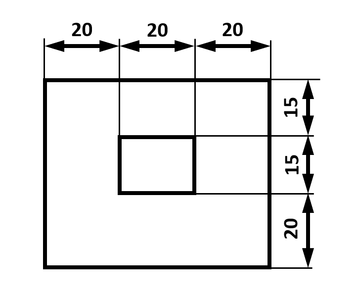
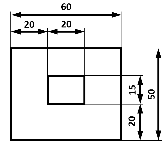
Now, in the same rectangular piece, a rectangular hole has been drawn. Both options are perfect:
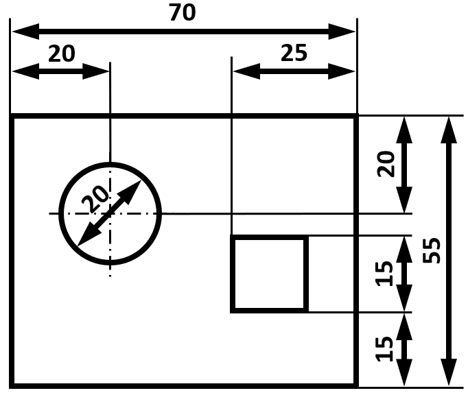
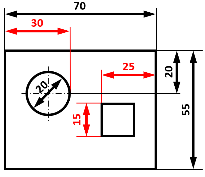
If there are more than one inner element the same procedure must be followed. Below you can see an examples with two inner elements (a circle and a square) as well as a wrongly dimensioned drawing on the right, with some of the most usual mistakes:


Dimensioning of small parts.
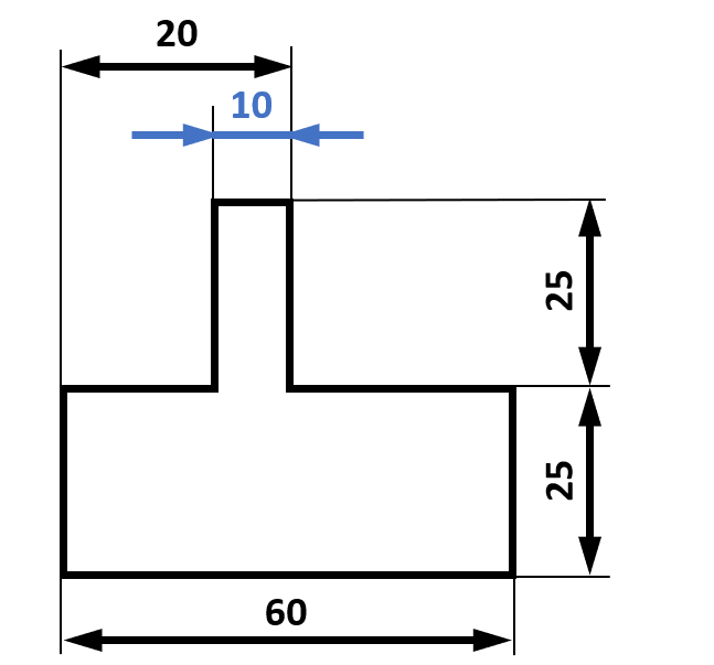
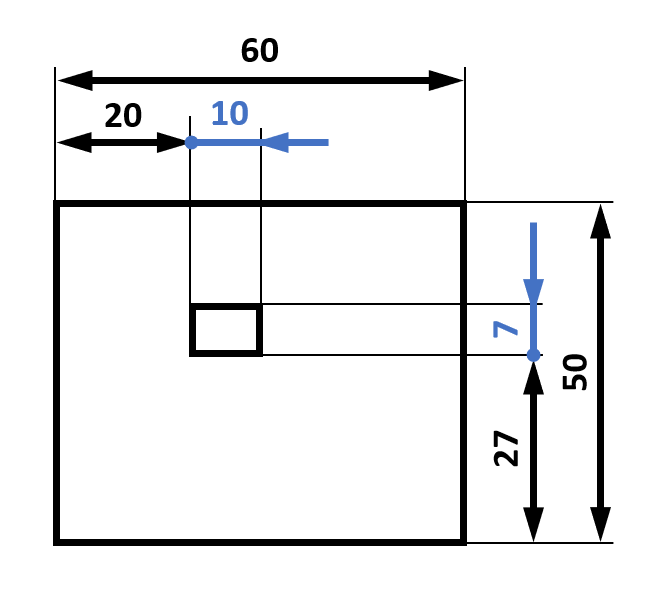
Sometimes the dimensions of some sides are too small to properly draw the arrows of the dimension line. In those cases, it is allowed to draw the arrows on the outside of the line, as indicated below (blue dimension lines). If necessary you can even omit one of the arrows and replace it with a dot (example on the right):
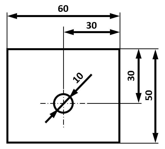
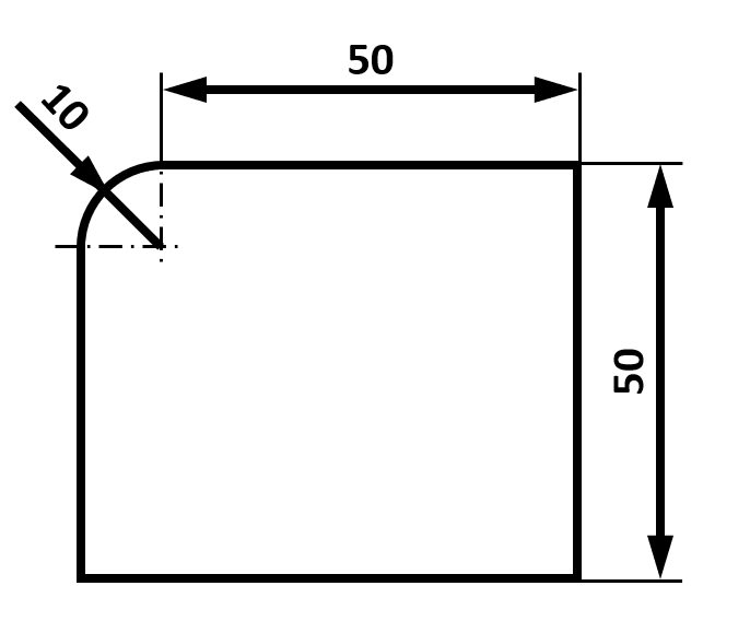
Just the same happens when circles or arcs are too small to draw the arrow in its inner part:
Dimensioning of slots.
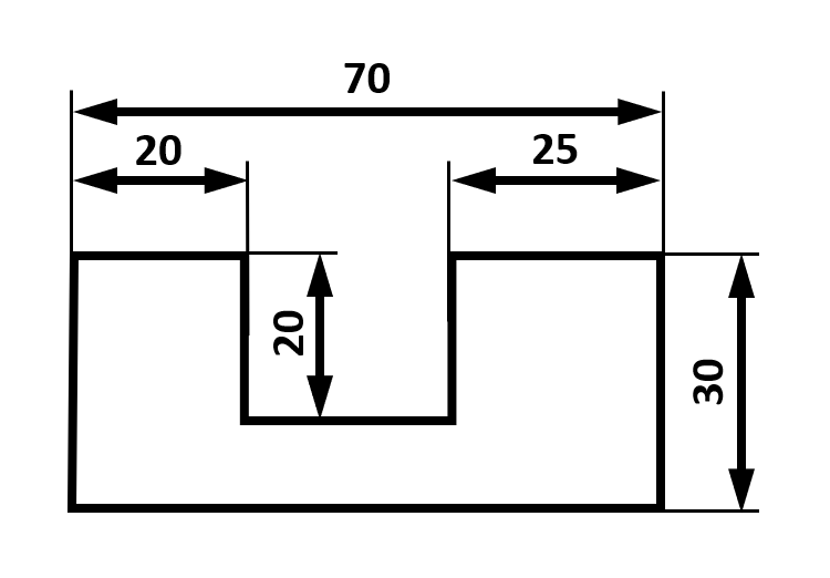
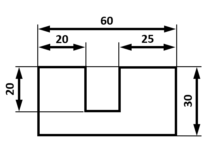
Sometimes figures have slots, that is parts that enter the figure. Depending on how narrow the slot is the dimension line that indicates its depth can be placed in the slot itself (image on the left) or outside the figure (image on the right):
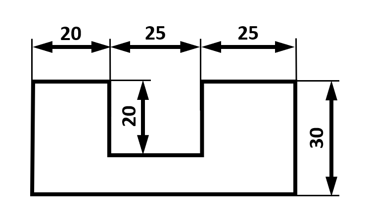
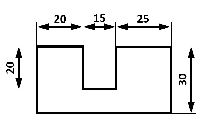
Of course, a parallel dimensioning is also correct: