Block 2: control of electronic components.

Write the Arduino programs that are necessary in each case and show them to your teacher.
Exercise 21: [easy]
Make a bulb connected to digital pin number 11 blink as in the gif: half a second on and half a second off. Example.

Exercise 22: [easy]
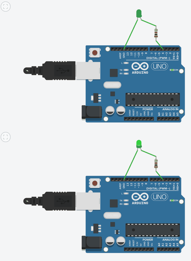
Make a green LED connected to digital pin number 4 blink as in the gif: one second on and two seconds off.
Exercise 23: [easy]
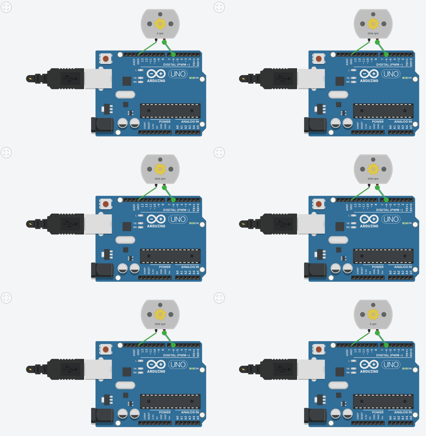
Make a motor connected to digital pin number 6 rotate as in the gif: half a second rotating and one and a half seconds stopped.
Exercise 24: [easy]
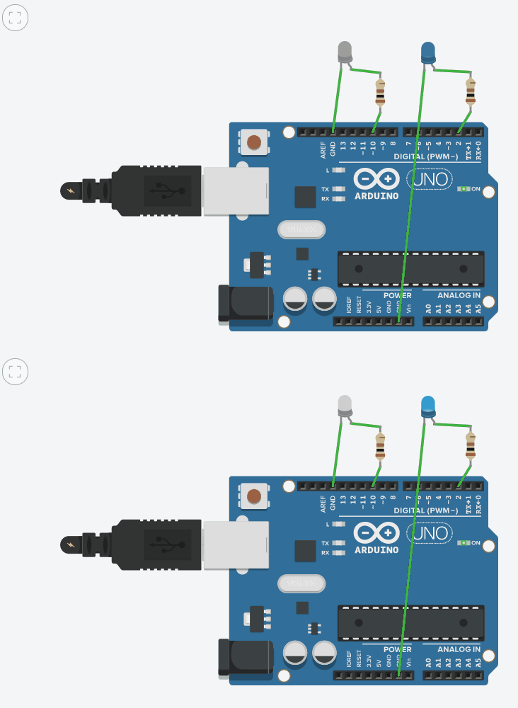
Make two LEDs connected to digital pins number 2 and 10 blink as in the gif: a quarter of a second on and a quarter of a second off.
Exercise 25: [easy]
Make two LEDs connected to digital pins number 4 and 9 blink as in the gif: first one of them blinks three times (one second on and one second off) while the other remains off and then just the opposite.
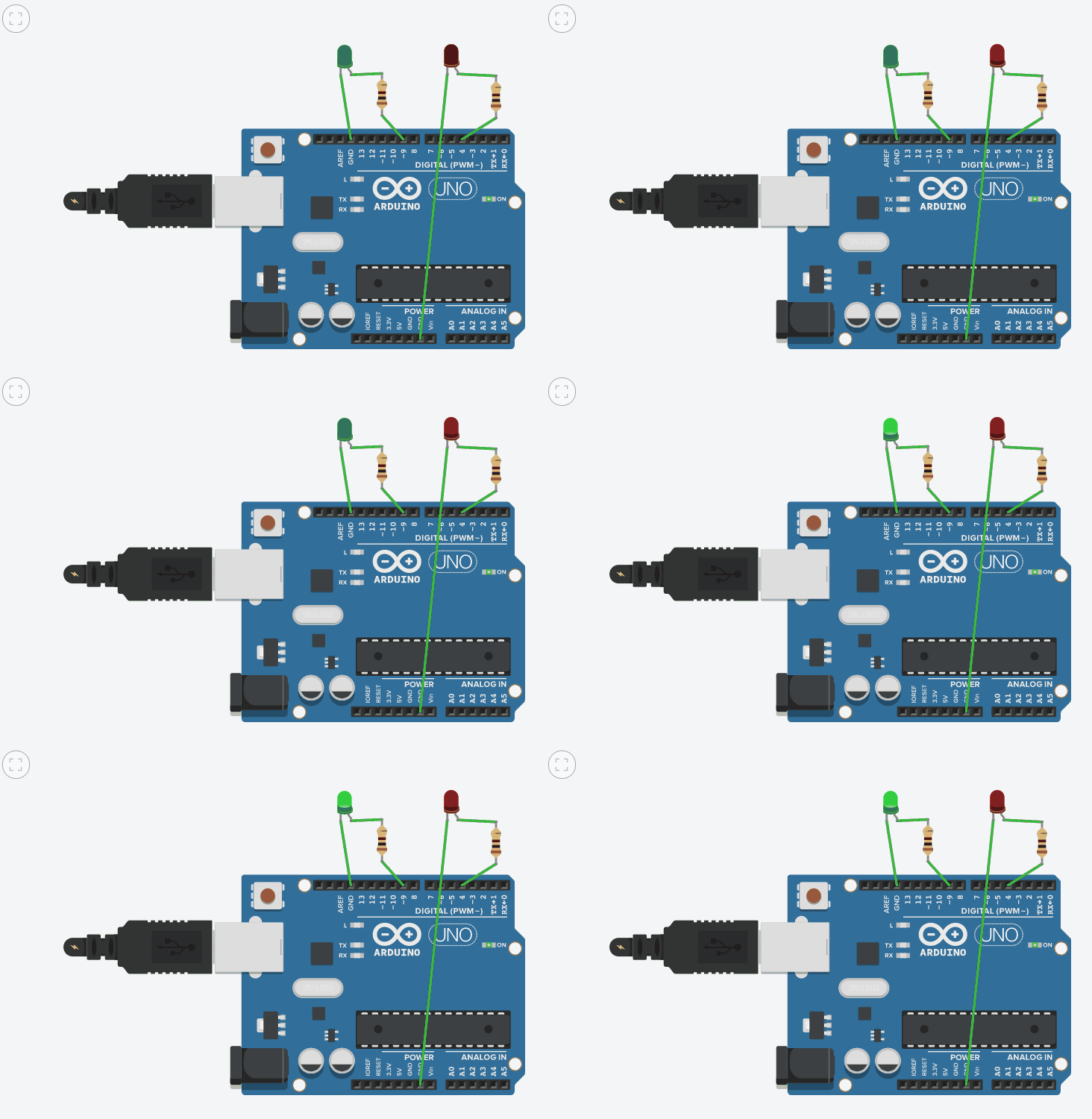
Exercise 26: [medium]
Make two LEDs connected to digital pins number 9 and 12 blink alternately as in the gif: while one is on the other is off and viceversa. Each LED must stay two seconds on and then two seconds off.
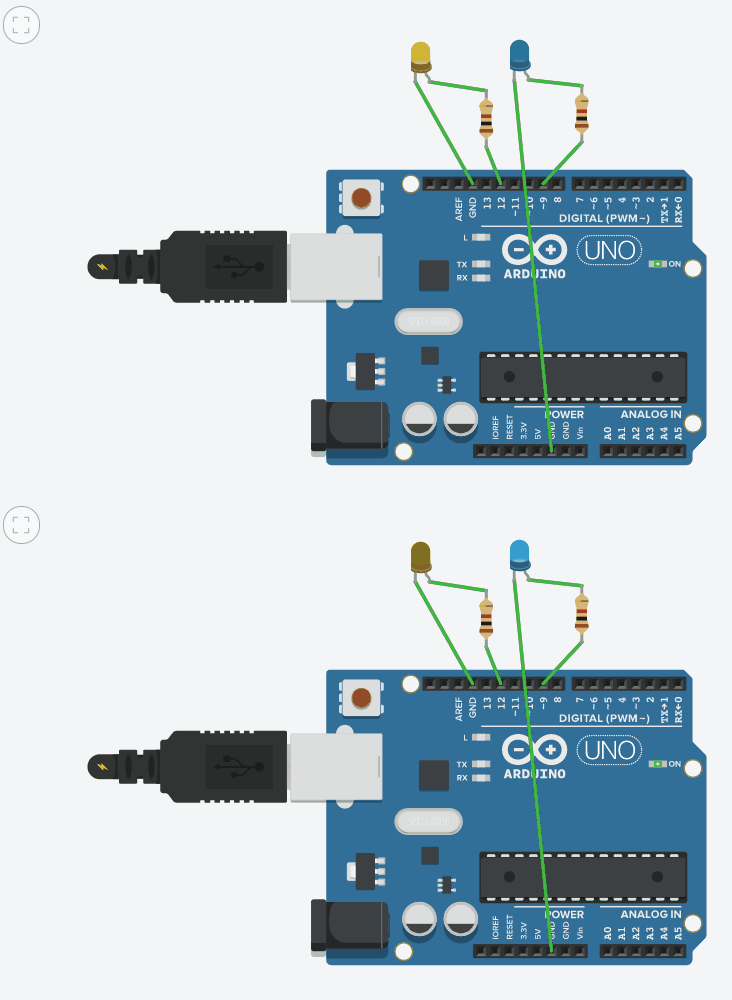
Exercise 27: [hard]
In this exercise, you must do the same as in the previous exercise but with three LEDs instead of two. It is very important that just one LED is on at each time (for two seconds).
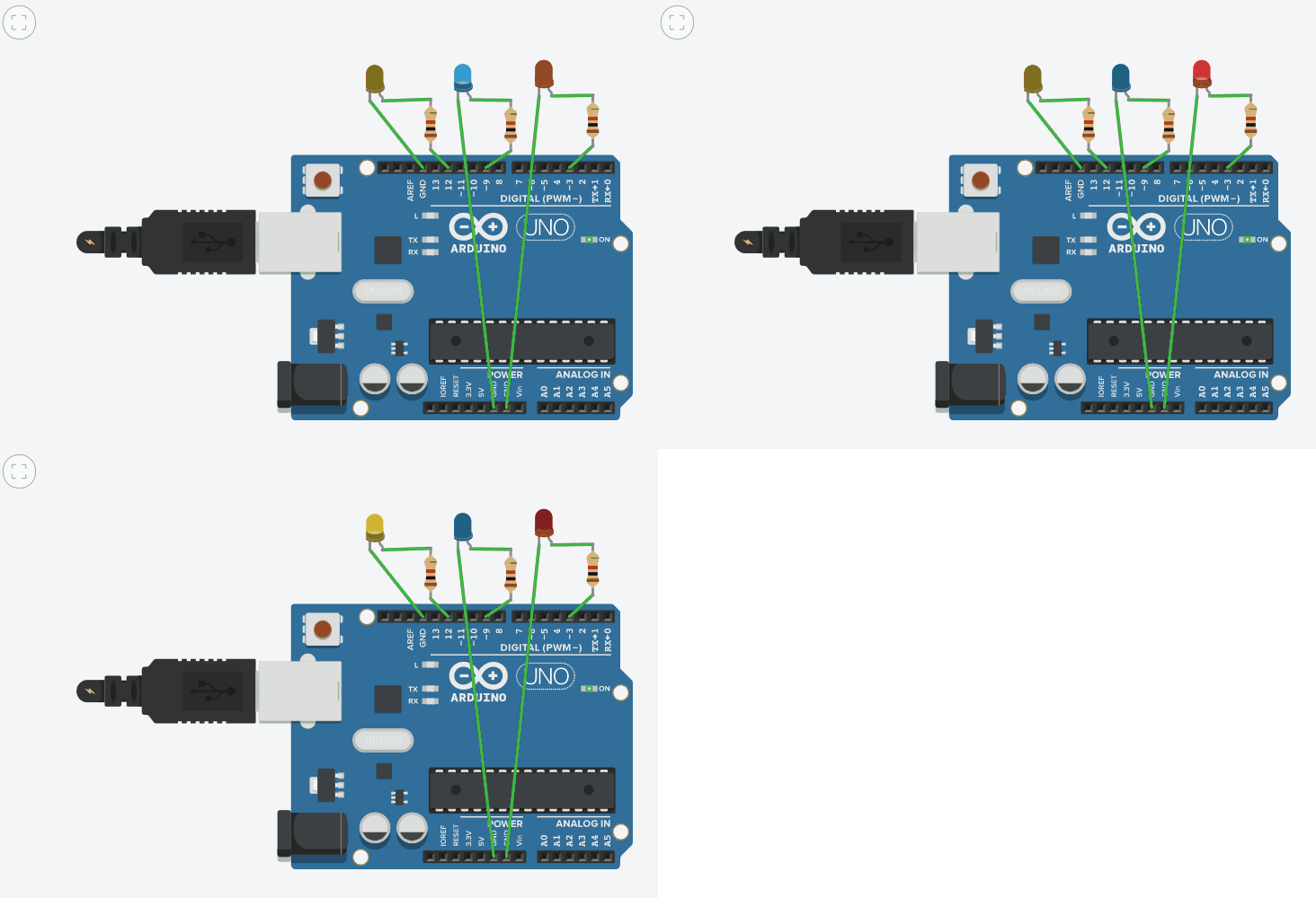
Exercise 28: [hard]
In this case, you must get the light to move to the left each half a second.
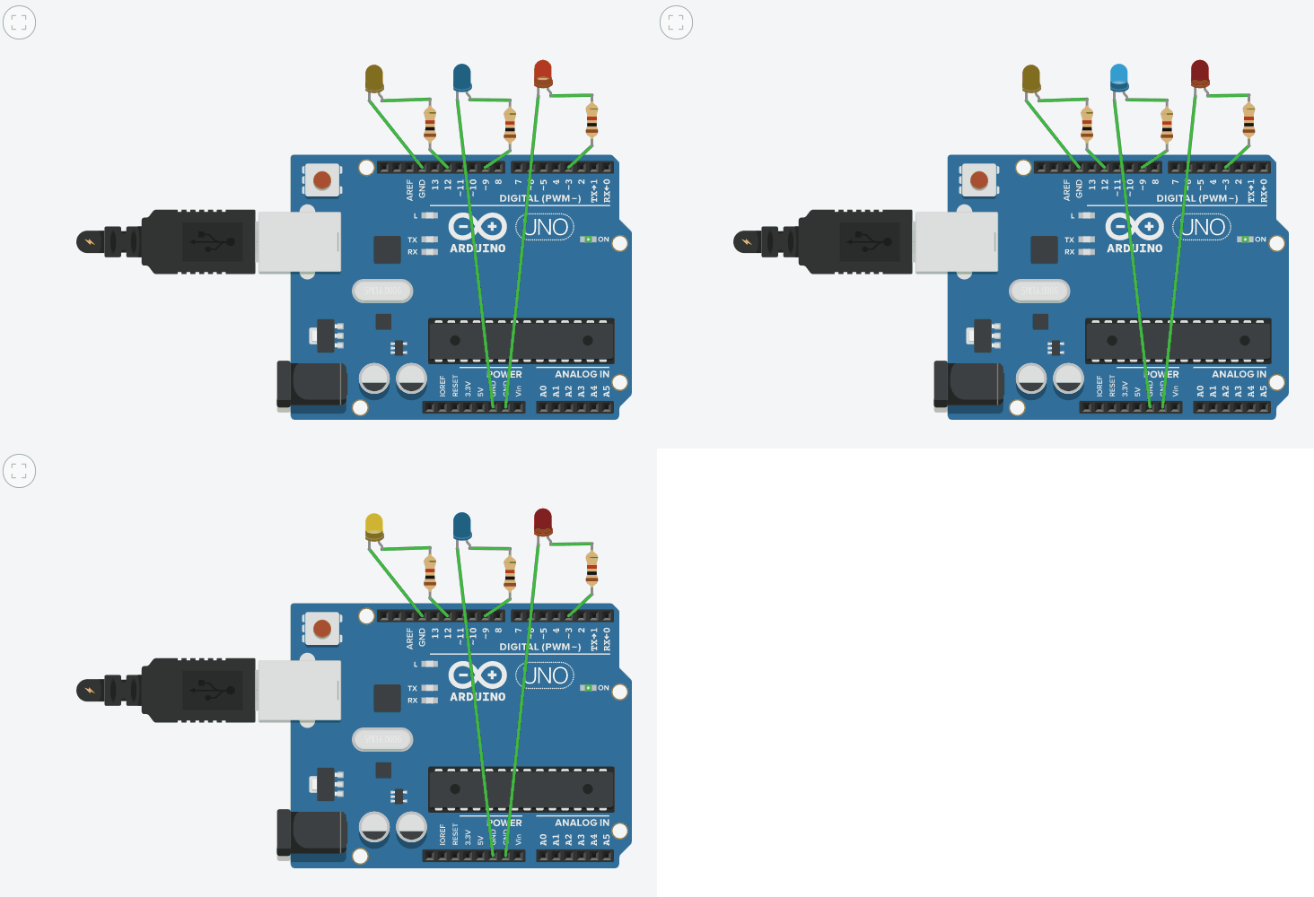
Exercise 29: [medium]
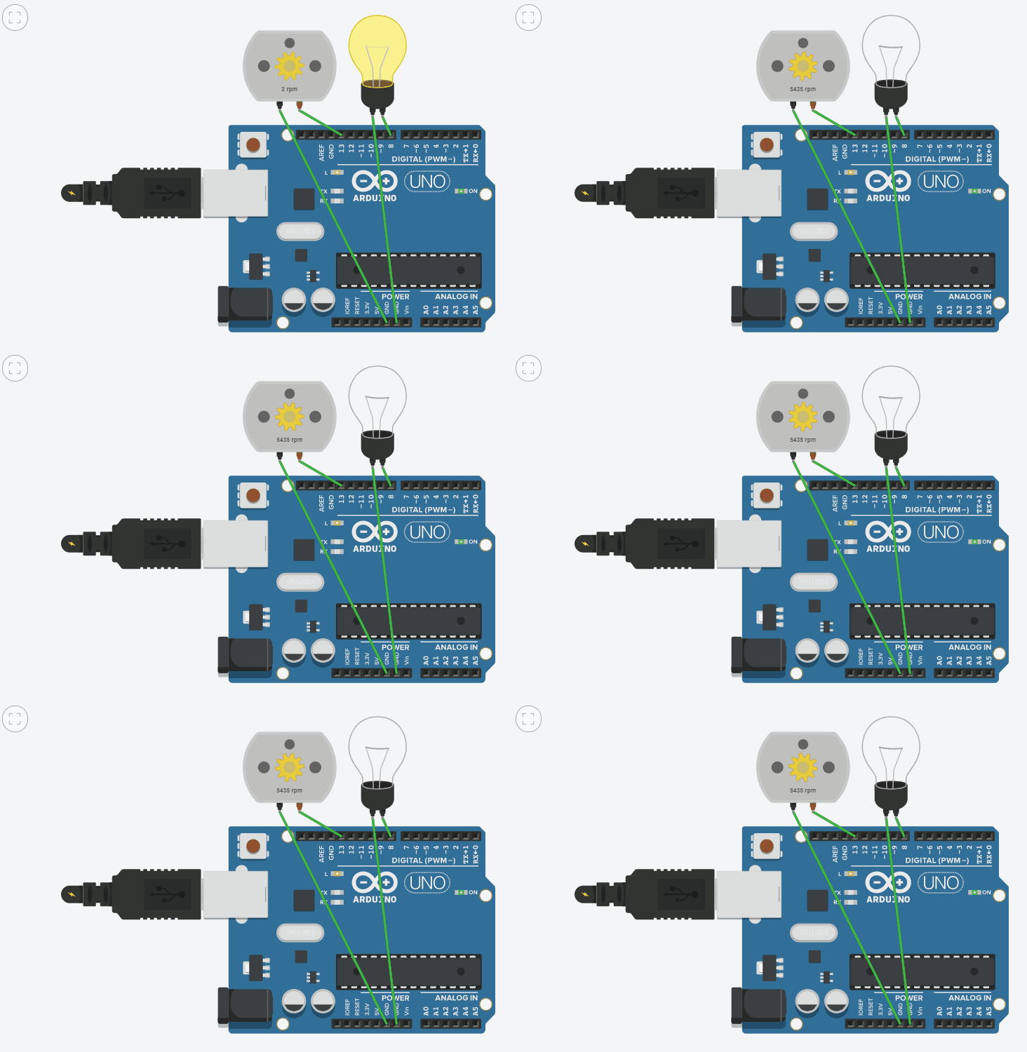
Connect a bulb to digital pin number 8 and a motor to pin number 13 and make them blink alternately like in the gif: the bulb each second and the motor every two seconds.
Exercise 30: [medium]
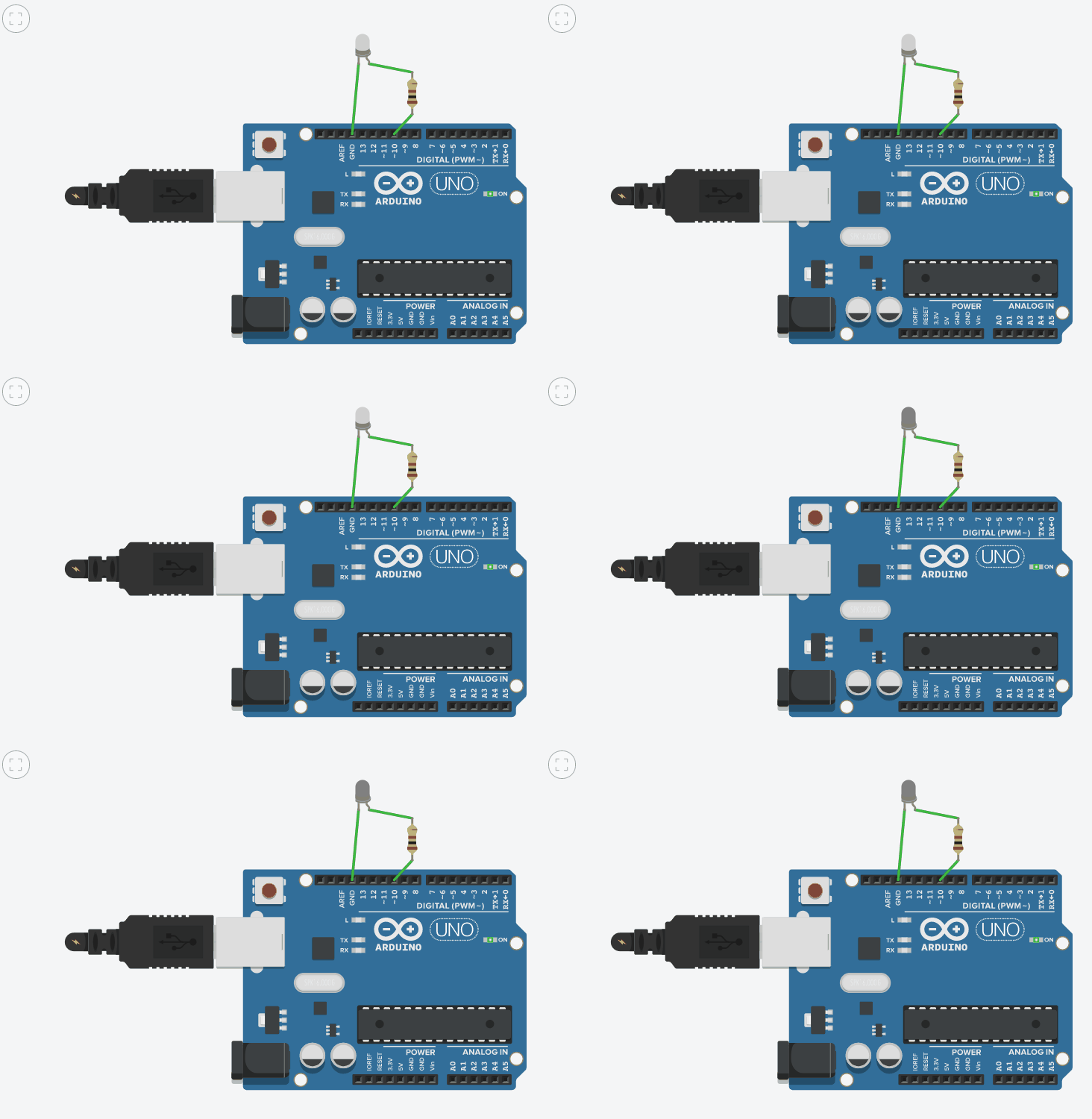
Get an LED to blink faster each time: first 2 seconds on and 2 off, then the same with 1.5 seconds, 1 second, 0.5 seconds and a 0.25 seconds.
Exercise 31: [medium]
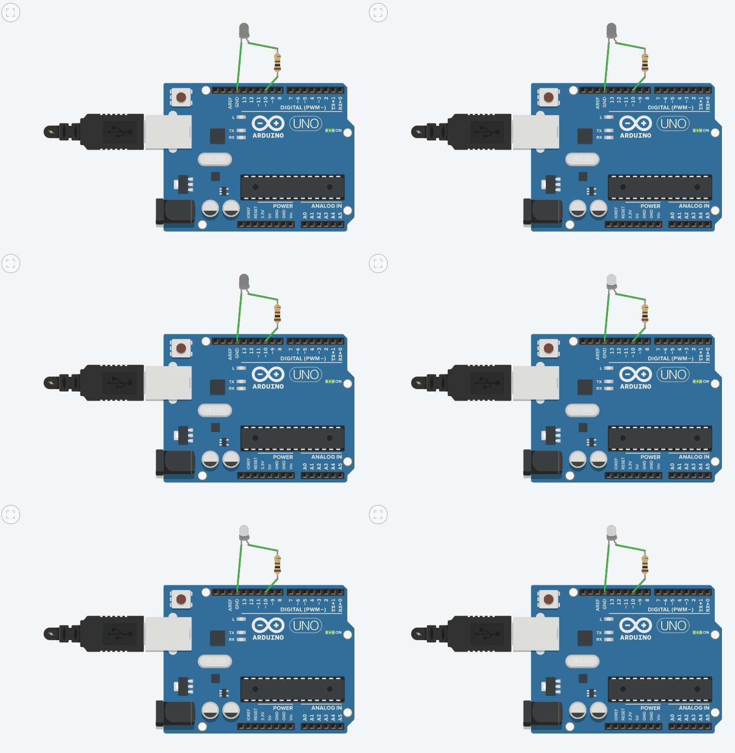
The same that in the previous exercise but each time slower:
Connect an RGB LED like this:
- Red LED to pin 12.
- Blue LED to pin 4.
- Green LED to pin 2.
- Negative terminal to any of the GND pins.
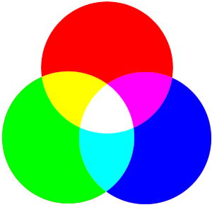
And then write the programs that make it blink as in the gifs. Remember that some colors can be obtained by mixing two or three basic ones:
Exercise 32: [easy]
Half a second on and half a second off with green light.
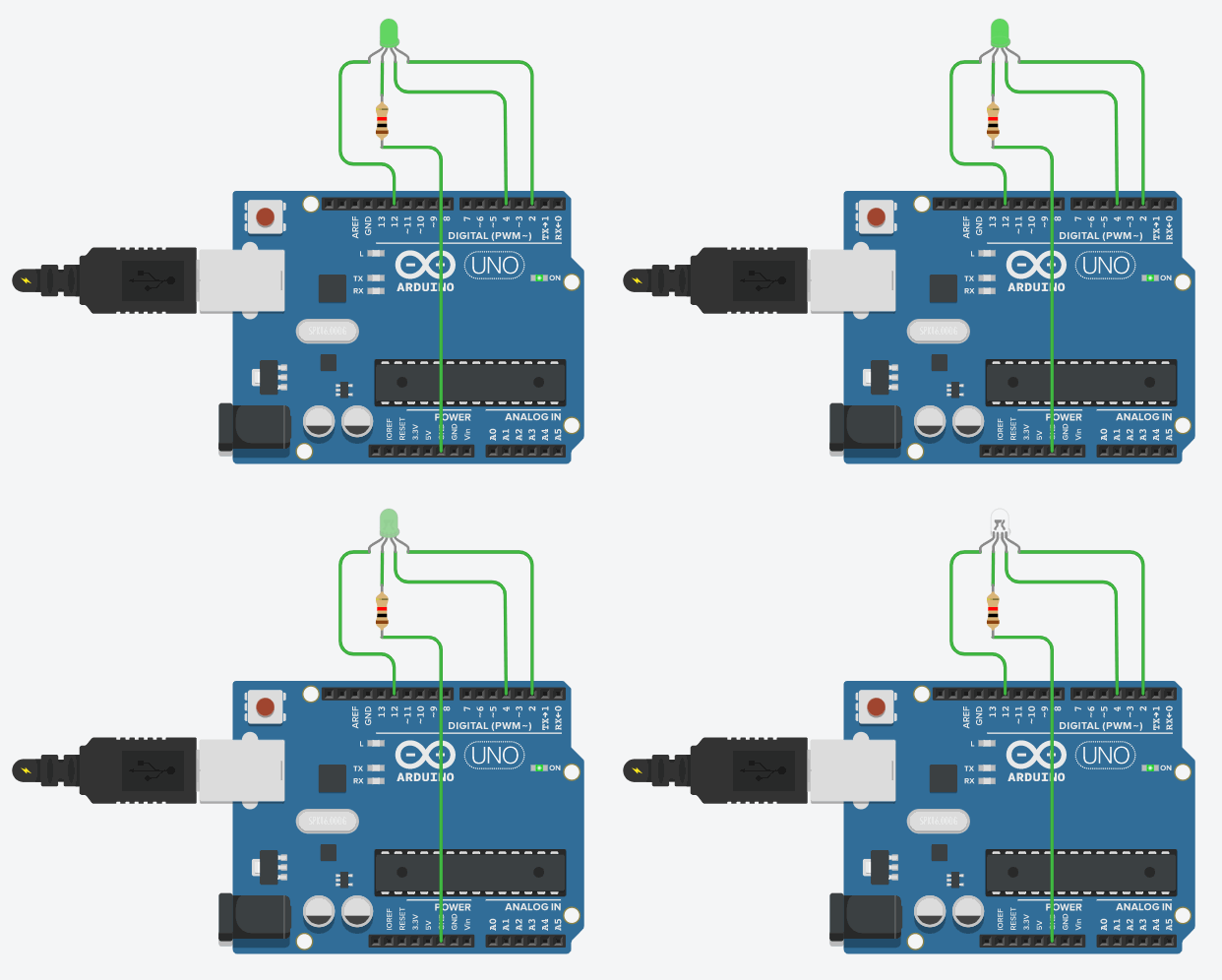
Exercise 33: [medium]
Two seconds on and two seconds off with pink light:
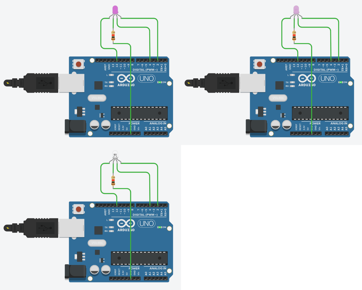
Exercise 34: [medium]
1,5 seconds on and 1,5 seconds off with white light:

Exercise 35: [medium]
One second on with red light and then one second off with white light. IMPORTANT: the change from one color to the other must be immediate so that the RGB LED is always emitting light of one or another color:
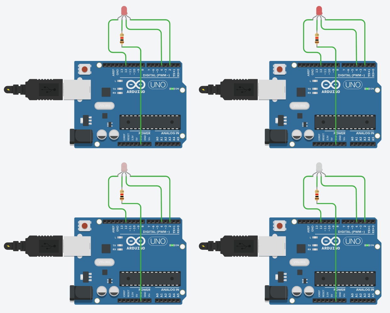
Exercise 36: [medium]
Half a second with yellow light, one second completely off and then half a second emitting light blue light:
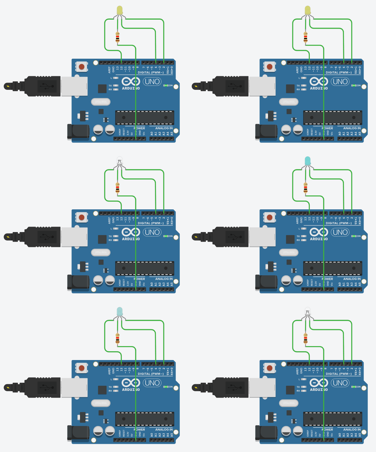
An LED display is an electronic device that allows you to show information in a very efficient way. The LED display that we are going to use has 7 segments and a dot, so both, numbers and letters, can be easily represented.
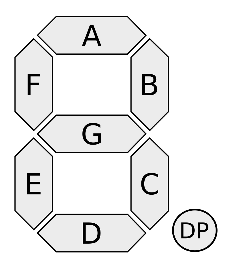
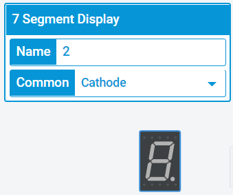
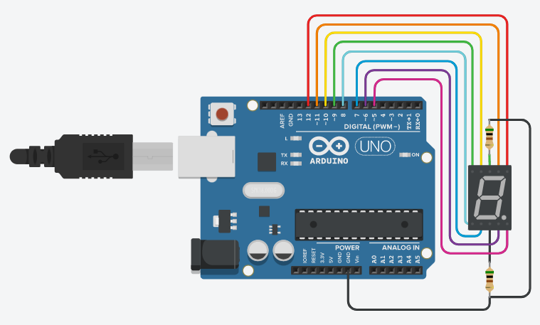
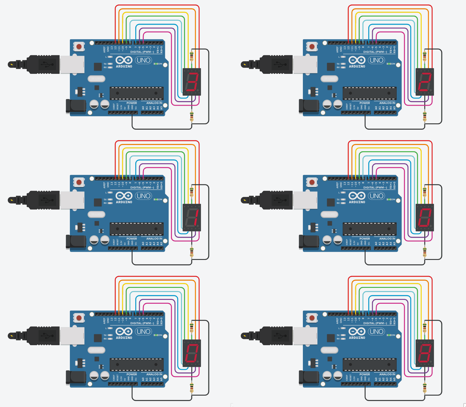
Each terminal of the display must be connected to a different PIN in Arduino, so that each segment can be controled individually. It is also important to connect the common terminals of the display to GND (if the common terminal is configured as the cathode) or to 5V (if the common terminal is configured as the anode). We are going to configure the common terminal, as shown in the image:
Exercise 37: [easy]
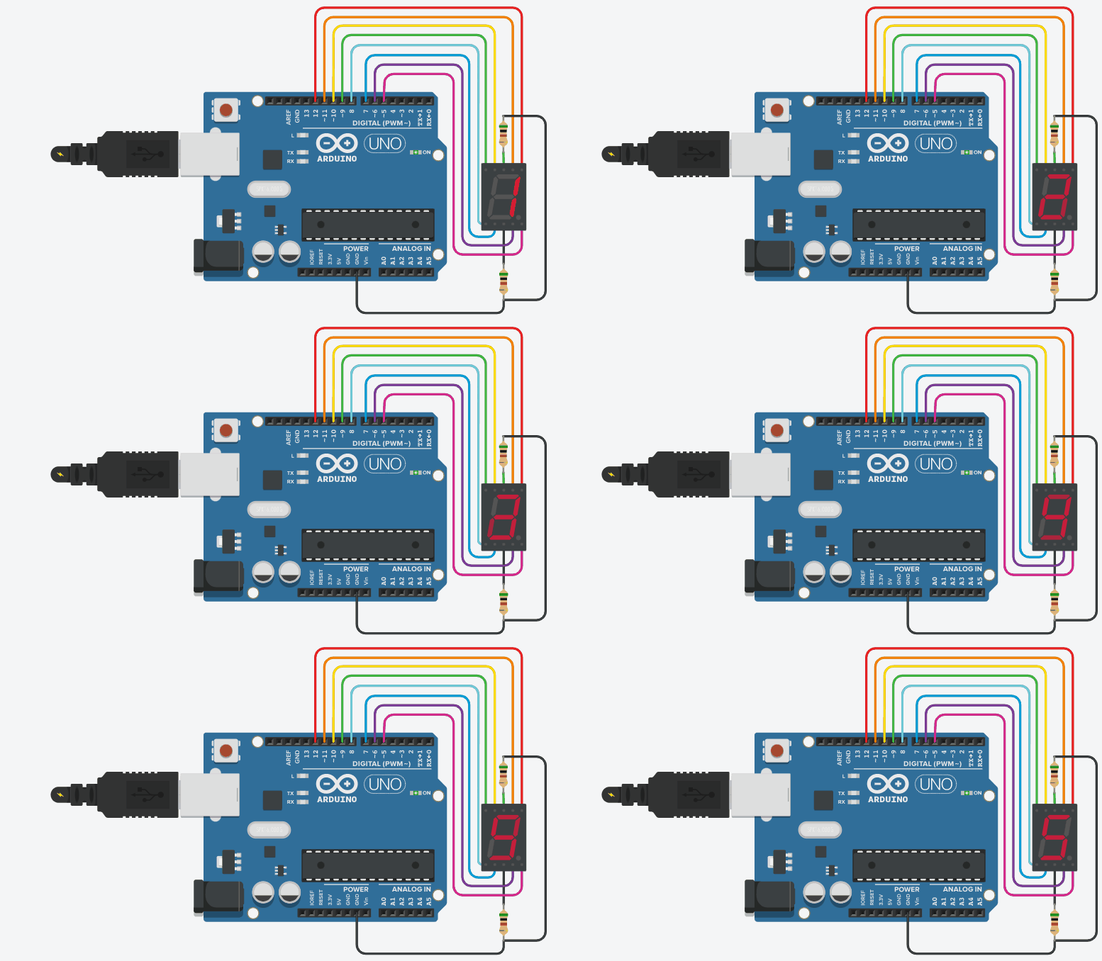
Write the program needed to show a counter from 1 to 5 on the LED display. Each number must be shown for one second.
Exercise 38: [medium]
Write the program needed to show a counter from 3 to 0 on the LED display. Each number must be shown for half a second.
Exercise 39: [hard]
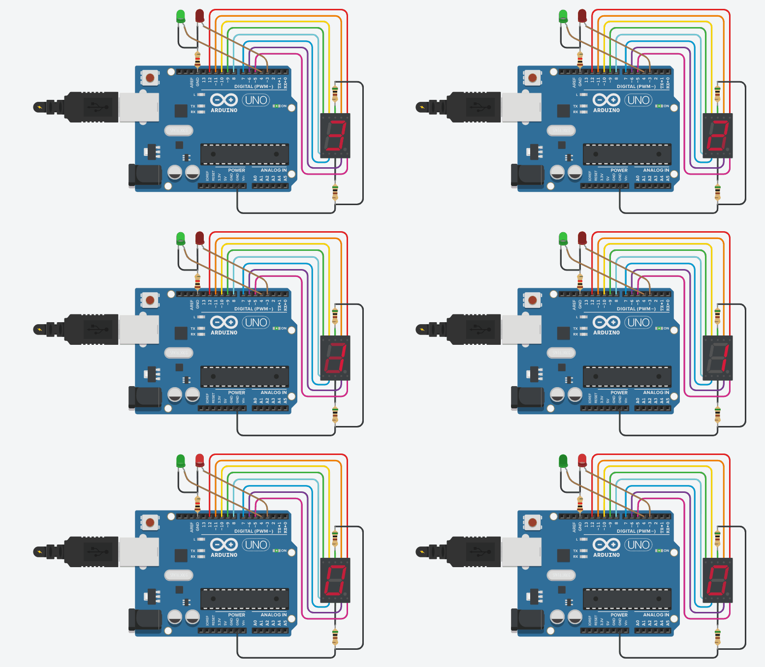
Write the program needed to show a counter from 3 to 0 on the LED display. Each number must be shown for two seconds. Apart from that, while numbers «3», «2» and «1» are shown, the green LED must be on and the red one must stay off. When number «0» is shown the red LED must turn on and the green one must turn off.
A servomotor is a special kind of motor that can be moved to a certain position or angle. They are used, for example, to make robotic arms in which common motors are not useful.
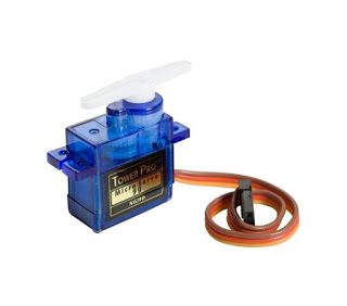
As it is shown in the image, servomotors have three terminals:
- Brown or black [ground]: that must be connected to a GND pin (negative pole of the battery.
- Red [energy]: that must be connected to the 5V pin (positive pole of the battery).
- Orange or white [signal]: that must be connected to a digital pin with the ~ symbol.
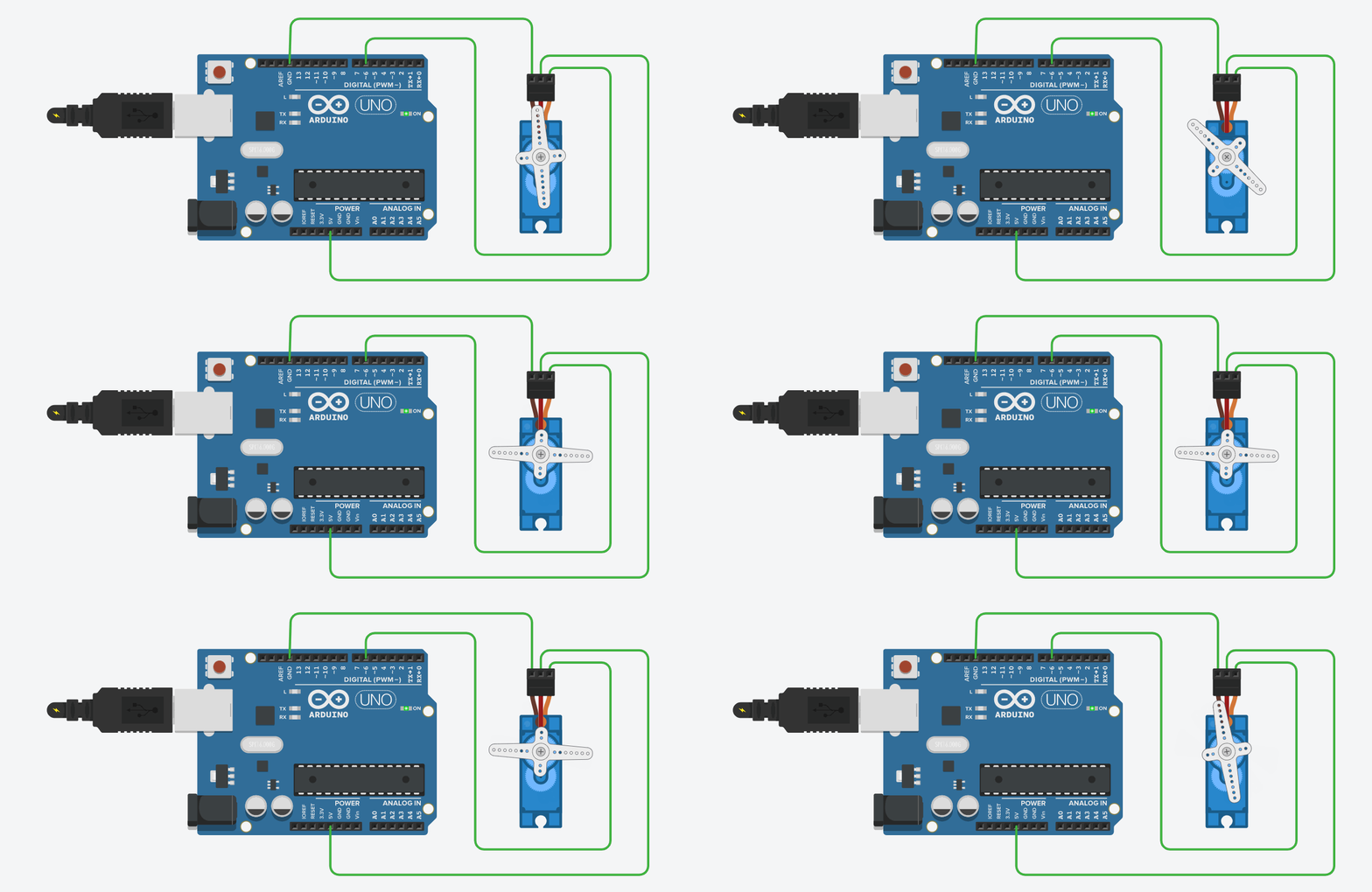
Connect a servomotor as indicated in each case and then program it.
Exercise 40: [easy]
Move one second to angle 0º and the during 2 seconds to angle 90º. Example.
Exercise 41: [medium]
Move from angle 0º to angle 180º in ten little movements each half a second, and the return back to angle 0º in just one movement.
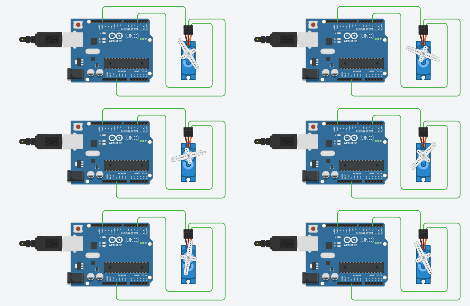
Exercise 42: [medium]
The same that in the previous exercise but making an LED connected to pin 12 light up for one second when angle 180º is reached:
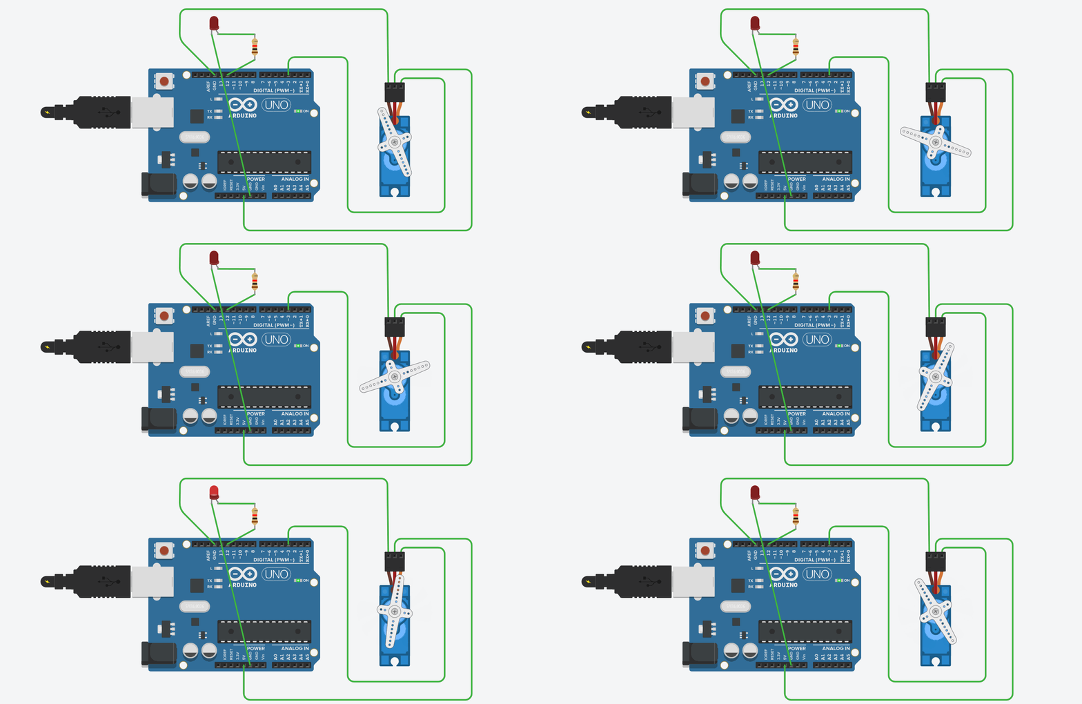
Exercise 43: [medium]
In this case, the servomotor moves from 70º to 100º each 1,5 seconds. Apart from that, a red LED turns on while the motor is moving towards 70º and a green LED turns on when the motor is moving towrds the 100º.

Exercise 44: [easy]
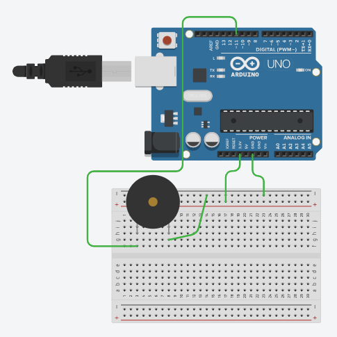
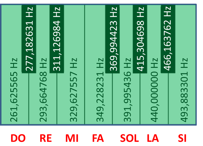
Make a buzzer connected to digital pin number 11 sound with the musical note do for 1 second and then with the note la for a quarter of a second once and again. Example.
Exercise 45: [medium]
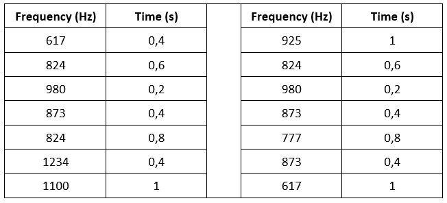
Make a buzzer, connected to pin number 10, play the melody whose frequencies and times are indicated on the table: